

『Flow Meter Rs485 Modbus Wiring: Connecting Multi-Drop Digital Serial Outputs to PLCs』Related information(flow rotameter|digital flow meter|balo meter|hydraulic flow meter|volumetric meter|positive displacement meter|pitot tube flow meter|displacement meter|cfm meter|variable area flow meter|inline flow meter|differential pressure flow meter|calibrated flow meter|velocity meter|paddle wheel flow meter|oval gear flow meter|anemometer hvac|multiphase flow meter|doppler flow meter|thorpe tube flowmeter|heat flow meter)

Flow Meter Rs485 Modbus Wiring: Connecting Multi-Drop Digital Serial Outputs to PLCs
Quick Answer: Flow Meter Rs485 Modbus Wiring is straightforward when you use daisy chain topology and correct termination. Use a shielded twisted pair for RS485 A and B plus a third wire for signal ground. Put a 120 ohm termination resistor at each end of the bus. Match baud rate, parity, stop bit, and Modbus slave ID between every meter and the PLC. Do not use star wiring.
Why RS485 Modbus Works for Multi-Drop Flow Meter Networks
Analog 4-20 mA outputs work well for one meter to one PLC input. A water plant in Malaysia with eight electromagnetic flow meters would need eight analog input cards. RS485 Modbus solves that. Connecting multi-drop digital serial outputs to PLCs over one two-wire bus means fewer I/O cards and simpler wiring. The PLC reads flow rate, totalized volume, temperature, and alarms over one serial link.
Silver Automation Instruments offers RS485 Modbus on electromagnetic flow meters, vortex flow meters, oval gear flow meters, and thermal mass flow meters. The wiring method is the same for all models.
Physical Layer and Cable Type
RS485 is a differential bus. Terminals are usually labeled A and B. Some devices use D+ and D- or TX+ and TX-. On most PLC and flow meter terminals, A is negative and B is positive. Here is the thing. Many engineers swap A and B during first commissioning. The hardware will not be damaged in most cases. The data just will not work. Swap the two wires and try again.
Use one shielded twisted pair for A and B. Add a third wire for signal ground. Some panels skip the signal ground. That works on short runs in a clean cabinet. On a real plant, noise from variable frequency drives causes Modbus timeouts. The signal ground wire fixes many of these faults. We have seen this on customer sites many times.
For runs over 50 meters, use cable with characteristic impedance around 120 ohms. Belden 3105A or similar is a good choice. For short runs inside a cabinet, ordinary twisted pair works.
Daisy Chain Topology and Cable Length
Run one cable from the PLC to the first flow meter. Run a short cable from the first flow meter to the second. Continue to the last flow meter. This is daisy chain topology.
Do not use star wiring. Star wiring means each flow meter has its own homerun cable back to a central terminal strip. Star wiring creates signal reflections. The bus may work at 9600 baud and fail at 19200 baud. Most engineers skip this part and then chase phantom communication errors.
Keep stubs under 20 cm. The main bus can reach 1200 meters at 9600 baud. At 19200 baud, keep it under 600 meters. At 38400 baud, keep it under 300 meters.
Termination and Biasing
Fit a 120 ohm resistor at both physical ends of the bus. One end is usually at the PLC. The other end is at the last flow meter. Many Silver Instruments flow meters include a termination switch or jumper.
If the PLC does not have built-in biasing, add two 680 ohm bias resistors. A resistor from B to +5 V and a resistor from A to signal ground keep the bus in a known idle state. This helps in high noise areas.
Modbus RTU Settings and Register Mapping
Set the same baud rate, data bits, parity, and stop bits on every device.
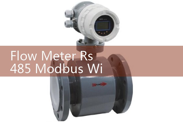
Give each flow meter a unique Modbus slave ID from 1 to 247. Do not use the same address on two meters. For Silver Instruments electromagnetic flow meters, flow rate and totalizer are available in Modbus RTU registers. The manual lists register addresses and data types. Check the byte order. Some PLC brands use big-endian and some use little-endian.
Connecting to PLCs
Many PLCs support Modbus RTU. Siemens, Allen Bradley, Mitsubishi, Omron, and Delta have RS485 ports or serial cards. The PLC A terminal goes to the flow meter A terminal. The PLC B terminal goes to flow meter B terminal. Signal ground connects all devices. If the PLC port uses a DB9 connector, check the pinout. Pin 3 and pin 8 are common RS485 pins on some brands but definitions vary.
A customer in Vietnam asked us last year why his flow meter worked on the bench but not at site. The issue was a long star-wired cable and missing signal ground. After rewiring in daisy chain and adding ground, the Modbus scan time dropped and the data was stable.
Power Wiring and Isolation
Flow meters with RS485 still need separate power. Do not use the RS485 signal wires to carry power. Many Silver Instruments electromagnetic flow meters accept 24 V DC. Some models accept 85 to 265 V AC. Keep the power cable at least 30 cm away from the RS485 cable. Cross at right angles if they must meet.
Use isolated RS485 transceivers when possible. Isolation prevents ground loops. A ground loop happens when two devices have different earth potentials. Current flows through signal ground and corrupts data. Many Silver Instruments flow meters include galvanic isolation between power supply and Modbus bus.
FAQ: Five Key Questions
Question 1: How many flow meters can be on one RS485 Modbus bus?
Up to 32 devices without a repeater. With a repeater, you can add more. Long cable runs and high baud rates reduce the practical number.
Question 2: Can I use CAT5 cable for RS485 Modbus?
Yes for runs under 30 meters. Use one twisted pair for A and B and one wire for ground. For longer runs, use low capacitance shielded twisted pair cable for RS485.
Question 3: What is the maximum cable length for RS485 Modbus?
The standard says 1200 meters at 9600 baud. At 19200 baud, keep the run under 600 meters. At 38400 baud, keep it under 300 meters.
Question 4: Why does my PLC show valid Modbus replies but wrong flow values?
Check the byte order of the 32-bit floating point values. Swap the high and low words in the PLC program. Also check the scaling factor in the flow meter manual.
Question 5: Do I need a termination resistor at every flow meter?
No. Only the two ends of the bus need a 120 ohm resistor. Do not terminate every device.
Need Help With a Specific Flow Meter Wiring Project?
Send us your PLC brand, flow range, pipe size (DN), pressure (bar), temperature (°C), and application. We will recommend a Silver Automation Instruments flow meter with RS485 Modbus output and the correct wiring set. Contact Silver Automation Instruments at Tel: +86-25-68650347, WhatsApp: +86-25-52155837, WeChat: +86 15365082610.
 Hot Product
 Related AD